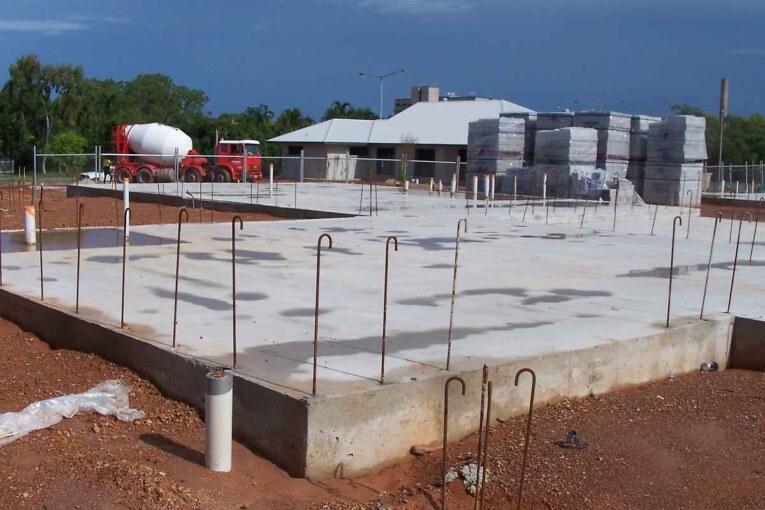
Excavation procedure for foundation construction requires site clearance, setting out, excavation and safety measures based on depth of excavation.
Site Clearance before Excavation for Foundation
Before the excavation for the proposed foundation is commenced, the site shall be cleared of vegetation, brushwood, stumps of trees etc. Roots of the trees shall be removed to at least 30 cm below the foundation level. The pits formed due to roots of trees, old foundations etc. shall be filled up with soil and compacted.
Setting out Foundation Layout for Excavation
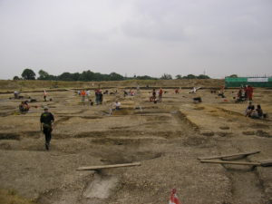
For setting layout of foundation excavation, a benchmark shall be established at the site by a masonry pillar and connected to the nearest standard benchmark. Levels of the site should be taken at 5 to 10 m intervals depending on the terrain and the importance of the building.
The centre lines of the walls are marked by stretching strings across wooden pegs driven at the ends. The centre lines of the perpendicular walls are marked by setting out the right angle with steel tapes or preferably with a theodolite.
The setting out of walls shall be facilitated by having a permanent row of pillars (not less than 25 cm side) parallelly laid at a suitable distance beyond the periphery of the building so that they do not foul with the excavation. The pillars shall be located at the junctions of the cross walls and external wall and shall be bedded sufficiently deep so that they are not disturbed during excavation for foundation.
The centre lines of the walls shall be extended and marked on the plastered tops of the pillars. The tops of the pillars may be kept at the same level, preferably the plinth level. In rectangular or square settings, the diagonals shall be checked to ensure accuracy of setting out.
Excavation Procedure for Foundation
For small buildings, excavation is carried out manually by means of pick axes, crow bars, spades etc. In case of large buildings and deep excavation, mechanical earth cutting equipment can be used.
For hard soils when the depth of excavation is less than 1.5 m, the sides of the trench do not need any external support. If the soil is loose or the excavation is deeper, some sort of shoring is required to support the sides from falling.
Planking and strutting can be intermittent or continuous depending on the nature of soil and the depth of excavation. In the case of intermittent or “open” planking and strutting the entire sides of trenches are not covered.
Vertical boards (known as poling boards) of size 250 x 40 mm of the required length can be placed with gaps of about 50 cm . These shall be kept apart by horizontal wailings of strong timber of section 100 x 100 mm at a minimum spacing of 1.2 m and strutted by a cross piece of 100 x 100 square or 100 nun diameter.
In the case of soft soils continuous or “close” planking is adopted and the vertical boards are kept touching each other without any gap as shown .
Open Planking for Excavations in Soft and Loose Soils
If the soil is very soft and loose. The boards shall be placed horizontally against the sides of the excavation and supported by vertical waling boards which shall be I strutted to similar timber pieces on the opposite side of the trench. Care has to he taken while withdrawing the timber members after completion of the foundation work so that there is no collapse of trench.
Dewatering of Excavation
Construction of foundation below the subsoil water level poses problems of waterlogging. It is therefore very often necessary to dewater the area of excavation.
Several operations have to be carried out within the excavation, like laying bed concrete, laying of RCC raft slab and construction of masonry etc. Therefore, work can be carried out more efficiently if the excavation area is kept dry.
Reduce Water Level below the Excavation Bottom
To keep the area of excavation dry, water table should be maintained at least 0.5 m below the bottom of the excavation. There are several methods available for lowering the water table. Information obtained from site and soil investigation would he useful in deciding the most suitable and economical method of dewatering.
Dewatering for Shallow Foundations
For fairly dense soil and shallow excavations, the simplest method is to have drains along the edges of the excavation and collect water in sumps and remove it by bailing or pumping. This is the most economical method and is feasible of being executed with unskilled labour and very simple equipment.
Dewatering for Large Excavations and Deep Foundations
Where large excavations such as for rafts are to be dewatered, wellpoint system can be employed. Wellpoint consists of a perforated pipe, 120 cm long and 4 cm in diameter with a valve to regulate flow and a screen to prevent entry of mud etc.
These wellpoints are installed along the periphery of the excavation at the required depth and spaced at about 1 m. The exact spacing can be decided on the basis of the type of soil.
Wellpoints are surrounded by sand gravel filter and have riser pipes of 5 to 7.5 cm diameter. These pipes are connected to a header pipe which is attached to a high capacity suction pump. The groundwater is drawn out by the pumping action and is discharged away from the site of excavation.
Concreting of Foundation in Excavation
In the case of a masonry wall, the footing is generally of cement concrete mix of ratio 1:4:8 or 1:5:10 (cement: sand: coarse aggregate). The size of coarse aggregate is limited to 40 mm. Lime concrete can also be used for this purpose.
For important works, mixing of concrete should be done in a mechanical mixer. Concrete should be laid (not thrown) in layers not exceeding 15 cm and well compacted.
The concrete should lie protected by moist gunny bags after about 1 or 2 hours of laying. Regular curing should be started after 24 hours and be continued for 10 days.
The masonry work over the bed concrete can be started after 3 days of laying the concrete but curing along with that of masonry shall be continued.
For RCC column footings and raft foundations, a levelling course of lean concrete of 75 rnm is laid in order to have an even and soil free surface for placing the reinforcement.

