Introduction
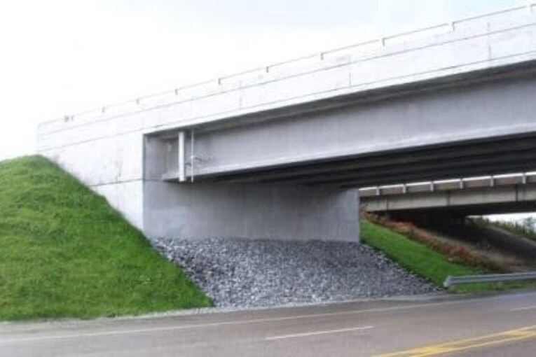
The design of the conventional bridges as multiple simply supported spans always prompted the bridge engineers to deliberately install various joints and bearings at the supports. This was to check and allow the displacements due to cyclic thermal loading. However, the introduction of moment distribution method in 1930 by professor Hardy Cross, contemplated with new avenues in bridge design. This paved way for use of integral abutment type bridges. Integral abutment bridges are continuous bridges, where the deck is rigidly connected to the abutments and approach slabs. This rigid connection allows integral bridges to act as a single unit in resisting thermal and axle loads. A typical integral abutment bridge system is shown in Fig. 1. The need for jointless bridges evolved from the desire to eliminate the use of expansion joints and bearings. Here, in such kind of bridges, superstructure is constructed integrally with the abutments and normally these abutments are supported by rows of vertically driven flexible piles. Integral abutment bridges have gained prominence throughout the United States from the 1930s and have since then become more common, especially for bridges with short, continuous spans. Traditionally the foundation of the abutments consists of a single row of flexible piles that are placed in pre augured holes up to a certain depth [10]. The holes are then backfilled with granular material. The pile heads are either fixed at the point of connection with the abutment walls or they are pinned. They also include an approach system where an approach slab is in immediate connection with the deck and abutment.
Types of Integral Bridges
Integrals bridges are classified into four types based on abutments types as follows:
- Integral Bridge with Frame Abutments
- Integral Bridge with Flexible Support Abutments
- Integral Bridge with Bank Pad Abutments
- Integral Bridge with Semi Integral End screen Abutments
Integral Bridge with frame abutments
A frame abutment effectively creates a portal frame with the bridge superstructure and retains the backfill behind the abutment. There is full moment continuity between the deck beams and the supporting structure at the ends. The supporting structure is founded well below the beams, either on a spread footing or on an embedded wall. Thermal expansion and contraction of the deck beams give rise to horizontal displacements at the top of the supporting elements, but at the base of these elements there is no horizontal sliding at the interface with the soil; the supporting elements must therefore flex. The presence of intermediate supports, in a multi-span bridge, does not alter the basic portal-type configuration.
Integral Bridge with Flexible Support Abutments
Although the soil resistance to the longitudinal displacement of fully embedded piles (due to expansion and contraction) is modest, many designers have chosen to avoid this interaction, and the tendency to create ‘post holes’ around them piles by creating an annular space around them, between the underside of the end screen wall and original formation level (or the level of the roadway below). This is achieved by forming sleeves of precast concrete manhole rings around the piles or, for smaller piles, of polythene or UPVC piping. The buckling resistance of the pile over the length within the annulus then needs to be considered. To improve confidence about the durability of the columns within the annulus, some Technical Approval Authorities require provision for the annulus to be inspectable (by boroscope or similar instrument) – this can be achieved by providing a duct from the end screen wall.
Integral Bridge with Bank Pad Abutments
One alternative to the creation of a stiff portal frame is to use bank pad abutments, in which the end supports are fully integral with the deck beams but are able to slide and rotate on the soil. Since the interface between the structure and the soil has to accommodate sliding (due to the thermal expansion contraction) and rotation (due to the bending of the deck beams), the soil bearing pressures at SLS will need to be limited to less than the normal ‘static’ values, to avoid the risk of degrading the bearing strength. A typical arrangement for a bank pad abutment is shown right.
Integral Bridge with Semi Integral End screen Abutments
In this configuration there is an end screen wall that is integral with the deck beams, but the wall does not provide support to the beams. Support is provided from some other structural arrangement, and with bearings that accommodate horizontal displacement. A piled bank pad or a retaining wall type support could alternatively be provided. In either case, the supporting structure is not displaced or subjected to rotation by the movements of the deck beams: the usual soil bearing pressures can be mobilised and there is no need to design for flexure or temperature effects.
Advantages of Integral Bridges
- Simplified details for construction.
- Reduced life cycle cost and long term maintenance.
- Improved design efficiency improved riding quality.
- Added redundancy with improved seismic performance ease in constructing embankments.
- Elimination of water leakage on critical structura l elements.
- Lesser tolerance restriction due to elimination of bearings and expansion joints.
- Faster construction
- Simplified widening and replacement detail useful for strengthening of existing bridges.
Disadvantages of Integral Bridges
- Integral body is geometrically very complicated and the detailed stress distribution can only be determined by the use of finite element methods.
- The stress distribution within the structure is not only a function of the applied loads but also of the relative stiffness of the many components.
- During an impact the body will crumple completely beyond repair, whereas in a body-on-frame, only the body will be damaged and the chassis can be reused.


