
1. INTRODUCTION
Most large electric motors run at nearly constant speed, although the equipment they drive – particularly pumps, fans, or blowers – represent loads that vary over time. Flow is regulated by partially closing a valve or damper in the system (throttling) or by allowing some of the flow to go through a bypass loop. These methods are effective, yet inefficient in terms of energy consumption of the system.
In Centrifugal Machinery, such as Fans, Blowers, Pumps, etc.the fluid flow is governed by the Affinity Laws.
Speed : N
Discharge : QαN
Head /Pressure : H αN*N
Power Consumption : P αN*N*N
If the Speed (N)of the Fan/Pump changes the discharge Quantity (Q) varies proportionately (linear), discharge -Head (H) varies in double multiple and the Power (P)consumption varies in triple multiples(Ref.Table.1)
Table.1
| Proportion of Max Flow | Flow Reduction | Power Consumed | Power Saved |
| (Flow1/Flow2) | (1-Flow1/Flow2) | (HP1/HP2) | (1-HP1/HP2) |
| 99% | 1% | 97% | 3% |
| 98% | 2% | 94% | 6% |
| 97% | 3% | 91% | 9% |
| 96% | 4% | 88% | 12% |
| 95% | 5% | 86% | 14% |
| 90% | 10% | 73% | 27% |
| 85% | 15% | 61% | 39% |
| 80% | 20% | 51% | 49% |
| 70% | 30% | 34% | 66% |
| 60% | 40% | 22% | 78% |
| 50% | 50% | 13% | 88% |
| 40% | 60% | 6% | 94% |
Adjustable speed drive technologies provide a better method of control by either varying the speed of the motor, as is the case with a VFD, or by providing a clutch between the motor and load to introduce some “slip” in the system, resulting in variable output drive speed. A number of different products fall into the latter category, where motor speed remains relatively constant and the speed of the output shaft is adjustable. These include variable diameter pulleys, mechanical clutches, fluid couplings, electromagnet eddy-current couplings, and permanent magnet adjustable speed drives.
2. DESIGN PRINCIPLE:
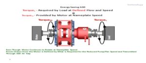
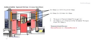
Magnetic torque transfer technology incorporates permanent magnets into a mechanical torque-transmitting device – a coupling or an adjustable speed drive (ASD). The permanent magnet coupling and permanent magnet ASD are constant torque devices that operate on the slip principle and are classified as a torque transmitter. This means that input and output torque are essentially equal and speed change is achieved by modifying the amount of torque transferred through the device. The device must slip in order to transmit torque, hence the difference in power is called slip loss, and is in the form of generated heat. There are also windage and frictional losses, but they are usually small enough to be neglected. Common values of slip for a centrifugal pump or fan application range from 1 to 4%. For most permanent magnet couplings and ASDs, slip heat is dissipated into the surrounding air by convection.
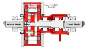
The magnetic technology utilizes powerful rare-earth permanent magnets to transmit torque across an air gap, allowing the input and output members to be mechanically independent. The permanent magnet coupling and ASD have two primary components. First, the magnet rotor assembly contains an aluminum magnet rotor populated with permanent magnets and is connected to the load (output) shaft. Second, the conductor rotor assembly is comprised of copper disks mounted to steel plates and is connected to the driver (input) shaft and rotates at constant motor speed.
The magnet rotor revolves freely within the conductor rotor. When the conductor rotor rotates relative to the magnet rotor, the magnetic flux from the magnet poles permeates the air gap and creates eddy currents in the copper conductor disks. The eddy currents create poles that interact with the magnet poles, whereby the magnetic flux develops a tangential force tending to turn the magnet rotor in the same direction as the rotating conductor. The net result is a torque available at the output shaft for driving a load. The magnet properties, rotor geometry, and materials of construction determine torque capability.
Rare-earth permanent magnets are made of a combination of neodymium, iron, and boron (NdFeB). The magnets are typically plated for corrosion protection. NdFeB magnets have a high energy product, permitting small size and high torque transmission capability, and they have a half-life of over 2,000 years.
2.1 Permanent Magnet Coupling
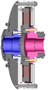
A permanent magnet coupling accomplishes the primary purpose of any conventional coupling, that is, to transmit rotary motion and torque from one piece of equipment to another. In addition, they perform a second important function – they accommodate unavoidable misalignment between shafts. Driver and load shafts are mechanically independent enabling the permanent magnet coupling to handle a fairly large degree of parallel offset, angular misalignment, and thermal expansion without transfer of forces/moments to the equipment shaft. Further, machine vibration is isolated from one piece of equipment to another and the cushioned start/stop capability reduces fatigue stress in the system. The permanent magnet coupling mounts directly to the driver and load shafts using keyed or shrink-disc coupling hubs, similar to a conventional coupling. A typical permanent magnet coupling is shown in Figure 3.
2.2 Permanent Magnet Adjustable Speed Drive
A permanent magnet ASD is used extensively to drive centrifugal pumps and fans in many applications where variable flow and pressure is required. Varying the width of the air gap provides adjustable torque and variable output speed to the load. The magnet rotors move axially about a center pivot to increase or decrease the width of the air gap between the conductor rotors, thereby varying the amount of torque transferred and providing speed control. The center pivot is locked onto a center shaft where a cam driver and follower allow positioning of the magnet rotors through uniform motion. The drive mechanism is actuated through an external control arm that is supported about the center shaft by a pair of antifriction bearings. The center shaft is fastened to the output member and properly aligned by a machined register fit to the shaft coupling hub. The permanent magnet ASD is available in horizontal and vertical configurations and they can be shaft mounted, same as a conventional coupling, or the drive may be mounted inside an enclosure, with two shaft extensions that are flexibly coupled to the driver and load shafts. Relative position between input/output rotors is maintained by the driver and load shafts, or when installed inside an enclosure, by a pair of rolling element bearings.
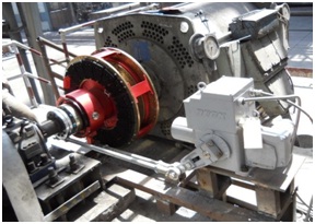
The movement needed to change the magnet rotor position and decrease/increase the output shaft speed is produced by an actuator. The type of actuator motion necessary to control the adjustable speed drive is either linear or rotary. A typical arrangement results from linear translating motion provided by a quarter-turn electric actuator working directly through linkage connected to the drive mechanism control arm. A feedback control loop can be added to the system that receives an input signal (4-20mA or 0-10VDC control signal) from a controller or process source and adjusts the drive’s output speed to a prearranged corresponding value. Air gap, output torque, and load speed are usually not proportional therefore; load torque characteristics and speed range must be known for proper permanent magnet ASD size and selection. A typical shaft-mount air-cooled permanent magnet ASD is shown in Figure 4.
2.3 Installation
The basic permanent magnet coupling and ASD is factory assembled and balanced. They can be installed indoor or outdoor without special provisions and can be installed and maintained by millwrights. Regular and preventative maintenance techniques are very similar to other types of couplings and rotating equipment. They are non-energized mechanical device; therefore, under normal operating conditions, it may be applied in hazardous services, and used in corrosive or explosive environments. Only the actuator needs to be rated for hazardous locations in order to place the drive within an explosive environment. General Service conditions for air-cooled permanent magnet devices are:
- Ambient Operating Temperature: (-30°C to 55°C).
- Humidity: 0 to 100% relative.
- Altitude : Does not limit performance.
Water cooled units require a supply of clean, potable water (flow per application) at 03-05kg/sq.cm and a maximum inlet water temperature of (27°C). Discharge (return) water at atmospheric pressure must be rejected on site, otherwise a coolant recirculation system is necessary. Applications below freezing require review of coolant type. Altitudes over 1065 meters also require review of coolant type or unit rating.
2.4 Benefits of the Technology
1. Improved Life, Maintenance and Reliability
Because a permanent magnet coupling and ASD transmit torque across an air gap rather than a direct shaft connection, they have certain unique characteristics that can extend equipment life, reduce maintenance costs, and increase the reliability of the motor-driven system. Each of the following benefits has the potential to extend the lifetime of one or more of the components in a motor-driven system, hence making the technology attractive for use with all types of rotating equipment.
2.Vibration Isolation – The permanent magnet device provides no mechanical path to transmit vibration from load to motor or vice versa, so it effectively attenuates vibration. Reducing equipment vibration will extend bearing life and lower maintenance and downtime costs.
3.Shock Load Tolerance – Some types of loads are subject to sudden and drastic changes in torque requirements. For direct-coupled equipment, shock loads can increase bearing wear, damage shafts and motor mounts, or cause the driver to lock up and potentially overheat. The permanent magnet device can accommodate the additional torque requirements of a shock load by a temporary increase in slip between the input and output members without affecting driver operation.
4.Misalignment Tolerance – Since there is no mechanical connection, the permanent magnet device can operate satisfactory despite parallel offset and angular misalignment. Elimination of the mechanical connection allows installations subject to thermal expansion, soft foot, system fluctuations and pipe strain to perform suitably with greater equipment reliability.
5.Cushioned Start – All permanent magnet devices provide cushioned start, a result of the slip between input and output members. The permanent magnet ASD can ramp a load up to full speed from a standstill with the motor operating at full speed continuously. This is advantageous for high starting-torque loads where it may be possible to specify smaller motors. Additionally, no-load or cushioned start/stop capability to the motor and load will reduce fatigue stress in the system, inrush current at start-up, and motor winding heat.
6.Power Quality – The permanent magnet device is non-energized, therefore, they are not vulnerable to process shutdown due to voltage sags, power fluctuations, and lightning strikes.
Harmonics – VFDs produce some level of harmonic currents from the way they pull current from a facility’s distribution system (e.g.: currents that oscillate at multiples of the 50- or 60-hertz fundamental). The permanent magnet ASD generates no electronic harmonic distortion and no voltage transients that are detrimental to the power distribution system or can disrupt electronic equipment.
7.Bearing Currents – Motors driven by VFDs can develop a non-zero voltage in the rotor relative to the grounded motor frame. The voltage discharges through the bearing, resulting in pitting (electrical fluting) of the bearing races and, over time, will degrade the bearing and lead to excessive vibration. This problem is eliminated with permanent magnet technology used in connection with a standard motor.
8.Cooling Requirements – The permanent magnet device is primarily cooled by convection into the surrounding air, even when exposed to high ambient temperatures. Higher horsepower permanent magnet ASDs require a continuous supply of cool water to draw out the slip heat generated during operation. It is not necessary to provide a climate controlled environment for a permanent magnet device.
9.Replacement Parts – The permanent magnet coupling has no wear parts and no contacting parts that would need replacement under normal operating conditions. The permanent magnet ASD is a mechanical device and replacement parts (seals, bearings, cam followers, etc.) are readily available. In comparison, it is extremely difficult to obtain parts for earlier technology eddy-current drives as well as the continuously evolving VFD technology (e.g.: obtain spare parts for older VFD drives when components like circuit boards fail).
10.Electromagnetic Interference (EMI) – For an assembled drive unit, electromagnetic interference is not a factor and is less than that typically found in an electric motor. However, for disassembled units, individual magnets and exposed magnet rotors require strict safety precautions and handling procedures – consult manufacturer for recommendations.
11.Consumables – The permanent magnet coupling does not require lubrication (grease) of any kind.
2.4.1 Key Features &Benefits
- Variable Speed Control
- Eliminates Valves and Dampers
- Significant Energy Savings
- Eliminates Electronic Harmonics
- No Physical Connection Between
- Motor and Load
- Lowest Total Cost of Ownership
- Efficient Torque Transfer
- Accepts Misalignment
- Cushioned and Delay Start
- Eliminates Vibration Transfer
- Between Motor and Load
- Permits Shock Loading
- Low Maintenance
- Simple Installation & Operation
- Increases Seal & Bearing Life
- “Green” Technology
2.5.0 Types of Conditions of Applications
- Vibration
- Periodic Load Seizure
- Pulsating & Shock Loading
- Thermal Expansion
- High Starting Inertia / Torque
- High Energy Costs
- Frequent VFD, Fluid Drive, & Eddy Current Drive Problems
2.5.1 Typical Applications of Machines
- Centrifugal Machinery (Pumps,Fans,Blowers,Centrifuges,etc)
- Variable Torque Machines/Equipments
2.5.2 Typical Applications of Industries
- Water & Wastewater
- Power Generation
- Mining & Cement
- Oil & Gas
- Chemical Processing
- Pulp & Paper
- HVAC
- Irrigation
- Maritime
- General Manufacturing
- Comparisonsof MagnaDrive(ASD) with VFD (Table.2)
Table.2
|
S. No |
Issues | Magna Drive (ASD) |
V.F.D |
| 1 | Motor & load Directly Coupled | No!
Torque transmitted through Air-gap which minimizes Vibrations and tolerates miss-alignment |
Yes! Creates Vibration transfer & misalignment problems |
| 2 | Life increase of Bearings,Seals and Equipment | Air gap minimizes harmful effect of vibration transfer and misalignment | No! Greater Vibration transfer and miss-alignment stresses decrease life. |
| 3 | Installation | Due to ‘disconnected nature’ASD is much more tolerant for misalignments. Low infrastructure.Simple mech.installation | Requires Infrastructure(Conduit,HVAC,Filters,Cabinets,etc.) Requires extensive alignment. |
| 4 | Sp. Requirements | Simple Mech.Equipment No Electronic components.Not affected by ‘dirty power’Doesnot require special Cooling cabinets or power control equipment.Retrofits easily. | Usually requires power filter equipment(VFDs are susceptible to dirty power)as well as Cooling Cabinets for Temp. & Dust control.Requires Inverter Duty Motors and other peripheral equipment. |
| 5 | O&M Issues | ASD is Green Product.No Harmonics or Electronic interference.Rapid restart capability.Long Motor life due to low incrush current. | Harmonics and Electrical System interference.Bearing ‘fluting’ decreases motor life and creates harmful vibration,frequent seal and bearing failures.Rapid component obsolescence.No quick restart capability.Short service life.Equipment Disposal issues.No over load protection. |
| 6 | Energy Efficiency | High! ASD is apprx.97% efficient. Min loss for water cooling above 500HP | Standalone VFDs are efficient.However dramatic energy efficiency losses occur with filters, transformers,cooling system, and other power conditioning equipment Inherent losses from system misalignment. |
- Indian Industries Using MTTT from M/s AVJ Engineering (Ref Table.3)
Table.3
| Sr. No. | Name of Customer | Location | Qty. | Application | Drive | Power in KW | Status |
| 1 | Delhi Jal Board | Delhi | 8 | Pump | Coupling | 290 | Installed |
| 2 | Bhilai Steel Plant | Coke Oven | 4 | Pump | Coupling | 45 | Installed |
| 3 | Bhilai Steel Plant | WMD | 6 | Pump | Coupling | 110 | Installed |
| 4 | Jindal Steel & Power | Power House | 1 | ID Fan | ASD | 190 | Installed |
| 5 | Tata Motors | Pune | 1 | Pump | Coupling | 15 | Installed |
| 6 | Tata Steel | PH-44 | 1 | Pump | Coupling | 75 | Installed |
| 7 | Tata Steel | Coal Plant | 1 | Conveyor | Coupling | 75 | Installed |
| 8 | Reliance Energy | CHP | 1 | Conveyor | Coupling | 110 | Installed |
| 9 | Bhilai Steel Plant | Sinter Plant | 1 | Conveyor | Coupling | 55 | Supplied |
| 10 | Bhushan Steel Ltd | Dewatering | 1 | Pump | Coupling | 18.5 | Installed |
| 11 | Infosys Ltd | ETP | 1 | Pump | Coupling | 7.5 | Installed |
| 12 | NALCO | CHP | 1 | Conveyor | Coupling | 37.5 | Installed |
| 13 | Tata Steel | Coke Plant | 1 | Crusher | Coupling | 550 | Installing |
| 14 | Jindal Power | Power House | 1 | DM T Pump | Coupling | 11 | Installed |
| 15 | Calcutta Electric Supply Company | CHP | 1 | Conveyor | Coupling | 45 | Installed |
| 16 | United Phosphrous Ltd | Comp House | 1 | Compressor | Coupling | 90 | Installed |
| 17 | Reliance Energy Rosa | CHP | 1 | Air Pre Heater | Coupling | 18.5 | Installed |
| 18 | Reliance Energy Dahanu | AHP | 1 | Ash Handling Pump | Coupling | 230 | Installed |
| 19 | NTPC Auraiya Gas Plant | Clarifier | 1 | Clarifier Pump | Coupling | 18.5 | Installed |
| 20 | NTPC Tanda Thermal Power Plant | CHP | 1 | Crusher | Coupling | 450 | Under Shipment |
| 21 | NTPC Tanda | CHP | 1 | Conveyor | Coupling | 110 | Installed |
| 22 | Infosys Bangalore | HVAC | 1 | Chiller Pump | Coupling | 18.5 | Installed |
- SOURCE OF SUPPLY
| MANUFACTURER
MAGNA DRIVE CORPORATION 14660 NE North Woodinville Way, Suite 100 Woodinville, WA 98072, USA Telephone: 425-463-4700, Fax: 425-487-3700 www.magnadrive.com
|
SUPPLIER
Vinod Malhotra Mobile:+919923413733,+919423573733 Website:www.avjengineering.com |
DISTRIBUTOR / DEALER
MagnaDrive Magnetic Couplings, Flownetix Ultrasonic Water Meters, Jyoti Pumps and Motors, ABB Make Electromagnetic Flow Meters, SILO under Ground Waste Collection Bins and Baldor Electric Pvt. Ltd. |
-
CASE STUDY OF J.S.P.L. RAIGARH
4.1 Introduction:
There are two nos. of I.D Fans in AFBC Boilers. It is the universal practice in big Boilers to provide two nos. of ID Fans Each ID Fan is designed to serve 60% of duty. Hence there has been scope for energy efficiency in I.D fan drives of Boilers.
Station : Power Plant-2 (Location: AFBC Boiler-2)
Name of Equipment : I.DFan 1B1
Drive Capacity : 190 kW
Voltage : 6.6 kV
FLC : 22 A
Normal Current : 15 A
4.2 Installation & Commissioning
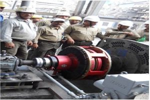
Name of the Job : Installation of Magna Drive (Adjustable Speed Drive-ASD 26.5)..(Ref.Picture.01&02)
Equipment Supplier : M/s AVJ Engineering& Marketing Pvt Ltd., Pune-411052
Retrofiting : Basement extended, Old Coupling Removed, Position-Controller tuned with DCS
Agency : In-house Efforts
4.3 Results—–Original Message—–
From: Vinod Ahirwar, Sent: 05 April 2012 10:58
To: PP#2 Control Room, Cc: Manish Khandelwal; MRL Sharma; MK Jaitwal; Praveen Saxena;RamaNadham
Subject: FW: Regarding power consumption`
Dear Sir,
Aux. Power cons. Of Blr-1 ID Fans (1A&1A1) for 24 Hrs. are coming 8000 Units.Also Aux. Power cons. Of Blr-2 ID Fans (1B & 1B1) for 24 Hrs. are coming 7000 Units it means 1000 units saving has been recorded with respect to working of ASD-26.5 (Magna Drive) in IDFan-1B1.
Regards,
VinodAhirwar (Sr.Manager,PP-II Electrical)
4.4 Savings / Returns / Payback
Energy Saving : 1,000 Unit/Day
Money Saving : Rs.3, 000/Day, (Rs.3×1000 Units)
Annual returns : Rs.10.5 Lacs, (Rs3000x355 days)
Capital Invested : Rs.21.9 Lacs
Simple Payback : 2 Years (approx.)
D.Rama Nadham
AGM-Power Plant,JSPL, Raigarh-496001
ABOUT THE AUTHOR
Mr. RamaNadham Devulapally had Graduted in Mechanical Engineering,B.Tech. from Jawaharlal Nehru Technological University, Hyderabad (AP) and had also acquired Diploma in Industrial Safety (DIS) from AnnamalaiUniversity,TN.Conferred as Chartered Engineer (C. Eng.) and also honored as Member (MIE) by Institution of Engineers (India),Kolkata. In addition, got ‘Boiler Operation Engineer-Proficiency’ (BOE) from Govt of Karnataka. And also an accredited Energy Manager & Auditor (EM&A) by Bureau of Energy Efficiency(B.E.E), Ministry of Power, Govt of India. And had involved in O&M of Power Plants and contributed innovations in the field of Energy Efficiency,Safety,Systemization,etc. and have been working in J.S.P.L Raigarh since 2005.

