Introduction
- An Architecture drawing is a technical drawing of building (or building falls within the definition of architecture).
- Architecture drawing are made according to a set of convention, which includes particular views like floor plan, section, sheet sizes, units, etc.
- Architectural drawing are use by architect to develop their design ideas to clients and also to communicate ideas and concepts.
Stages of Architecture Drawings
- Initial Sketch Plans
- Developed Designs
- Final Plans and Specification
Initial Drawing Plans
- Sort out what you like and what you want to change.
- Consider some of the technical limits.
- Discuss with designer about environmental conditions.
- Look at your budget.
- Ask about future maintenance issues.
- Decide if you feel comfortable.
Developed Designs
- Draw up the development designs.
- Design is particularly a cutting-edge.
- Discuss the materials use- cladding, flooring, roofing, roofting, windows, doors.
- Interior fittings and fixtures- power points, cable jacks, exterior taps, light location and attic access.
- Use a quantity surveyor to estimate the cost of the project.
Final Plans and Specifications
- In the tendering process, get quotes from contractors, subcontractors and also quantity surveyors.
- Builder and contractors contracted to build house as blueprint for the construction.
Important Points
- Floor plan
- Site Plan
- Elevation
- Cross Section
- Isometric and Axonometric Projections
- Detail Drawings
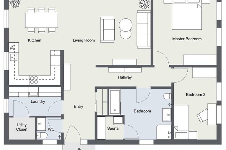
1. Floor Plan
- Floor plan is a most fundamental architectural diagram.
- Showing the arrangement at a particular level of a building.
- 3 feet/ 1 meter above floor level.
- Floor plans includes anything.

2. Site Plan
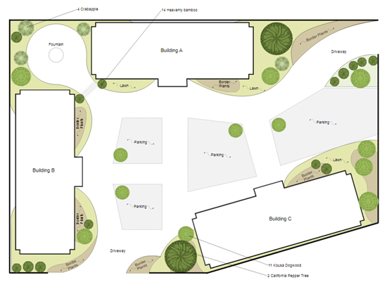
- Site plan is an architectural plan, landscape architecture document, and a detailed engineering drawing.
- A site plan usually shows a building footprint, travel ways, parking, drainage facilities, sanitary sewer lines, water lines, trails, lighting, and landscaping and garden elements.
3. Elevation
- Elevation drawing that shows the front or side of a building.
- Without elevation drawings, you cannot see the details of your new cabinetry, the size of each drawer or the location of each cabinet.
- Elevation is not require for every renovation or redecorating project, they are very useful when designing items like a fireplace, bathroom vanities, bars, or any location with built-in cabinetry, such as an office or entertainment space.

4. Cross Section
- A cross section, also simply called a section, represents a vertical plane cut through the object, in the same way as a floor plan is a horizontal section viewed from the top.
- Everything cut by the section plane is shown as a bold line, often with a solid fill to show objects that are cut through, and anything seen beyond generally shown in thinner line.
5. Isometric and axonometric Projections
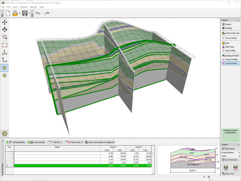
- A simple way of representing a three dimensional object.
- An isometric uses a plan grid at 30 degree from the horizontal in both directions, which distorts the plan shape.
- An axonometric uses a 45 degree plan grid, which keeps the original orthogonal geometry of the plan.
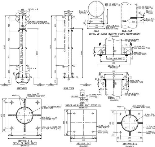
6. Detail Drawing
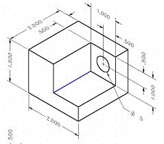
- Detail drawings provide a detailed description of the geometric form of a part of an object such as building, bridge, tunnel, machine, plant, and so on.
- They tend to be large-scale drawings that show in detail parts that may be included in less detail on general arrangement drawings.
